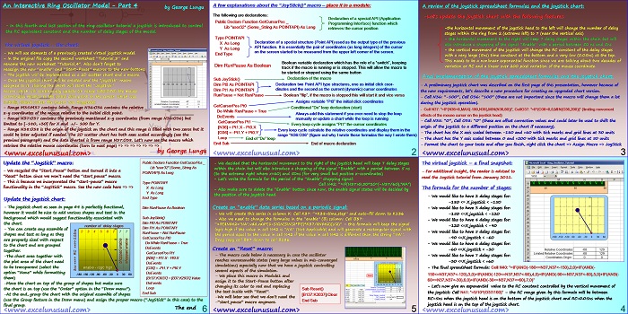
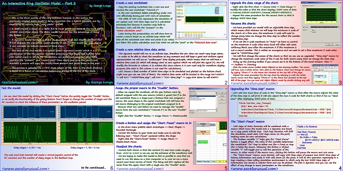
This is the first part of tutorial explaining how to make an interactive animated Excel model of a gated ring oscillator in MS Excel 2003.
Like most of the models on this site this model will run fine in newer Excel versions too. A delay based model was used for the logic gates which was previously discussed.
An Interactive Ring Oscillator Model – Part 1
by George Lungu
– In this tutorial, an animated gated ring oscillator model is created. The model used gates
(several inverters and one NAND gate) having a delay based scheme of operation which was
analyzed in the previous series of lectures.
– The general oscillator theory will not be given here. The readers are encouraged to update
their knowledge from other sources if they wish.
What is a ring oscillator?
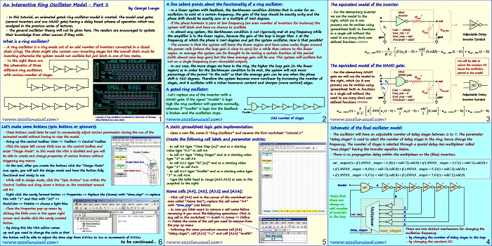
– A ring oscillator is a ring made out of an odd number of inverters connected in a closed
chain (ring). The chain might also contain non-inverting stages but the overall chain must be
inverting otherwise the system would not oscillate but just latch in one of two states.
– To the right there are
the schematics of three
different ring oscillators
with various number of stages.
Layouts of ring oscillators produced at University of Chicago
(https://fabweb.ece.uiuc.edu/)
A few salient points about the functionality of a ring oscillator:
– In a linear system with feedback, the Barkhausen condition dictates that in order for an
oscillation to exist at a certain frequency, the gain of the loop should be exactly unity and the
phase shift should be exactly zero or a multiple of 360 degrees.
– If the phase however is zero at low frequency (an even number of inverters for instance) the
system will latch and have no chance to oscillate
– In almost any system, the Barkhausen condition is not rigorously met at any frequency while
the amplifier is in the linear region, because the gain of the loop is larger then 1 at the
frequency at which the phase is 360 degrees and yet the system oscillates. How is that possible?
– The answer is that the system will leave the linear region and have some nodes linger around
the power rails (where the loop gain is close to zero) for a while then return to the linear
region. In average the system can be thought to be resting a certain fraction of the period
(with almost zero loop gain) but the time average gain will be one. This system will oscillate but
not on a single frequency (non-sinusoidal output).
– In our case, the more stages we have in the ring, the higher the loop gain (in the linear
region) so in order for the Barkhausen condition to be met, the system will rest more
percentage of the period “in the rails” so that the average gain can be one when the phase
shift is 360 degrees. Therefore the system becomes more nonlinear by increasing the number of
stages, and it oscillates with a richer harmonic content and sharper (more vertical) edges.
A gated ring oscillator:
-Let’s replace one of the inverter with a
NAND gate. If the signal “Enable” is logic
high the ring oscillator will operate normally,
whereas if “Enable” is logic low the feedback
Enable
is broken and the oscillation stops.
Odd number of stages
The equivalent model of the inverter:
– For the elementary inverter Ideal
Inverter
we use the model to the
A out
right, which (as it was out
proven) can be written using => RC
spreadsheet built-in functions
Gain = – infinity V out_INV
Cout
in a single cell without the Vout_min = 0
Adjustable Delay
Vout_max = vdd
gnd
need to use (very slow) user
Threshold = vdd/2 Inverter Symbol
defined functions =>>>>>
We will be able to
adjust the constant RC
The equivalent model of the NAND gate:
hence the oscillation
– For the elementary NAND Ideal period in the model
NAND gate
gate we will use the model to
the right, which (as it was
B VA out
proven) can be written using => RC
VB
spreadsheet built-in functions
Gain = – infinity V
out_INV
Cout
in a single cell without the Vout_min = 0
Adjustable Delay
Vout_max = vdd
need to use (very slow) user gnd gnd
Threshold = vdd/2 Inverter Symbol
defined functions =>>>>>
Schematic of the final oscillator model:
– The oscillator will have an adjustable number of delay stages between 2 to 7. The parameter
“delay_stages” is used to select the number of delay stages in the ring, hence change the
frequency. The number of stages is selected through a special delay-less multiplexer called
“mux_stages” having the transfer equation below.
– There is no propagation delay within the multiplexer or the (blue) inverters.
out _ stages t)
Enable A
RC
*Note that B
there are
always an
odd number C
of inverters D
out_mux
E
in the loop
F
G
There are two distinct mechanisms for changing the
delay_stages
mux_stages
oscillation frequency:
– by changing the number of delay stages in the loop
– by changing the constant RC.
A static spreadsheet logic gate implementation:
– Open a new file, name it “Ring_Oscillator” and rename the first worksheet “Tutorial_1”
Create the following cell labels and parameter entries:
– In cell A3 type “Time Step [ns]” and as a starting
value type “0.1” in cell A4.
– In cell A7 type “Delay Stages” and as a starting value
type “2” in cell A8.
– In cell A11 type “RC [ns]” and as a starting value
type “1” in cell A12.
– In cell A15 type “Enable” and as a starting value type
“1” in cell A16.
– Type the table head in range [A35:J35] as seen in the
snapshot to the right.
Name cells [A4], [A8], [A12] and [A16]:
– Click cell [A4] and in the corner of the worksheet (an
area called “Name Box”), replace the cell name “A4”
with “time_step” (see below).
– In case you later want to remove a cell name before
renaming it you must the following operations: Click in
any cell in the worksheet => Insert => Name => Define
=> Delete the name of the cell you need to remove from
the pop up menu
– Following the same procedure rename cell [A8]
“delay_stages”, cell [A12] “r_c” and cell [A16] “enable”.
Let’s make some buttons (spin buttons or spinners):
– These buttons could later be used to conveniently adjust various parameters during the run of the
animated model without having to stop the model.
– Bring up the control toolbox: View => Toolbars => Control Toolbox
– Click the upper left corner little icon on the control toolbox and
enter “Design Mode”. In this mode the VBA is disabled and you will
Control Toolbox
be able to create and change properties of various buttons without
triggering any macro.
Design Mode Icon
– At the end, after you create the buttons click the “Design Mode”
icon again, you will exit the design mode and have the button fully Spin Button Icon
functional and ready to use.
– While still in design mode, click the “Spin Button” icon within the
Control Toolbox and drag-draw a button on the worksheet around
cell B4.
– Right click the newly formed button => Properties => Replace the (Name) with “time_step” => replace
Min with “1” and Max with “20” =>
BackColor => Palette => choose a light blue
– Close the Properties pop up menu by
clicking the little cross in the upper right
corner and double click the newly created
button.
– By doing this the VBA editor comes
up and you need to change the code so that
the button will be able to adjust the time step from 0.05ns to 1ns in increments of 0.05ns
to be continued…


