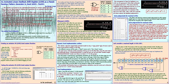
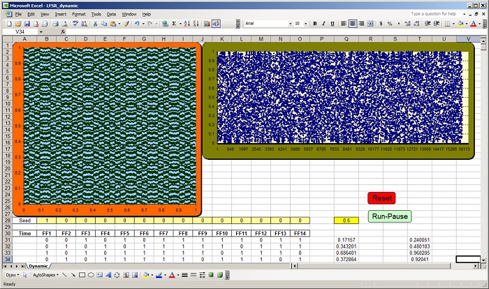
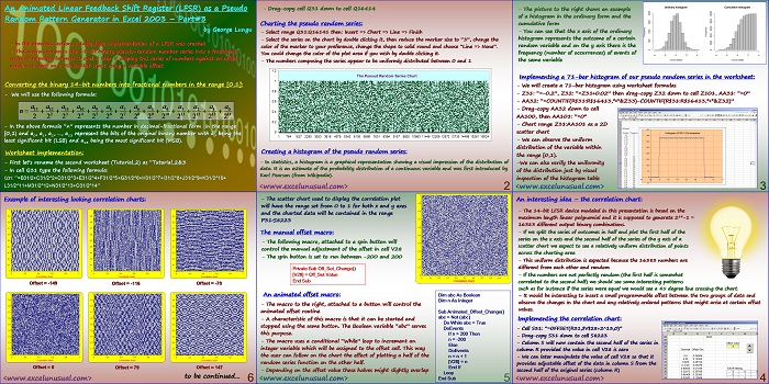
This is the first part of a tutorial (self, 2, 3) describing the creation of an animated Pseudo Random Number Generator model as a Fibonacci type Linear Feedback Shift Register in MS Excel 2003.
![]()
An Animated Linear Feedback Shift Register (LFSR) as a Pseudo Random Pattern Generator in Excel 2003- Part#1
by George Lungu
– This tutorial is not meant to be a theoretical introduction to random number generation
but a mere cook-book recipe for building such a generator as an animated Fibonacci type
LFSR in Microsoft Excel 2003.
– A very sketchy theoretical introduction is given after which a 14-bit long Fibonacci type
LFSR device is implemented in a worksheet having feedback which generates a maximum
length sequence (214-1).
– This type of device is covered in most undergraduate curricula in schools such as Electrical
Engineering, Computer Engineering and Computer Science.
– Being a while since I myself studied this device in school and having a very limited time
budget I briskly refreshed my memory from Wikipedia:
(https://en.wikipedia.org/wiki/Linear_feedback_shift_register)
and used their Fibonacci setup and their formula table for a maximum sequence 14-bit
LFSR.
An outline from Wikipedia:
– A linear feedback shift register (LFSR) is a shift register whose input bit at any time is
a linear function of its previous state.
– Applications of LFSR’s include generating pseudo-random numbers, pseudo-noise
sequences, fast digital counters, and whitening sequences. Both hardware and software
implementations of LFSR’s are common.
– The mostly used linear function of single bits is XOR, INPUT OUTPUT
thus normally it is a shift register whose input bit is A B A XOR B
driven by the exclusive-or (XOR) of some bits of the
overall shift register value.
The symbol of a
– The initial value of the LFSR is called the seed and
XOR gate and because the operation of the register is deterministic, its truth table
the stream of values produced by the register is completely determined by its current (or previous) state.
– Likewise, because the register has a finite number of possible states, it must eventually enter a
repeating cycle. However, an LFSR with a well-chosen feedback function can produce a sequence of bits
which appears random and which has a very long cycle.
Fibonacci LFSR’s:
-The bit positions that affect the next state are
called the taps. In the diagram the taps are
[16,14,13,11]. The rightmost bit of the LFSR is
called the output bit. The taps are XOR’d
sequentially with the output bit and then fed back
into the leftmost bit. The sequence of bits in the rightmost position is called the output stream.
– The bits in the LFSR state which influence the input are called taps (white in the diagram).
-A maximum-length LFSR produces an m-sequence (i.e. it cycles through all possible 2n − 1 states
within the shift register except the state where all bits are zero), unless it contains all zeros, in which
case it will never change. The sequence of numbers generated by an LFSR can be considered a binary
numeral system just as valid as Gray code or the natural binary code
-The arrangement of taps for feedback in an
LFSR can be expressed in finite field arithmetic
as a polynomial mod 2. This means that the
coefficients of the polynomial must be 1’s or 0’s.
– This is called the feedback polynomial or
characteristic polynomial. For example, if the
taps are at the 16th, 14th, 13th and 11th bits x16 + x14 + x13 + x11 + 1
(as shown above), the feedback polynomial is:
Some polynomials for maximal LFSRs:
-The table to the left lists maximal-length polynomials for shift-register
lengths up to 15. Note that more than one maximal-length polynomial
may exist for any given shift-register length.
Some polynomials for maximal LFSRs:
-Ones and zeroes occur in ‘runs’. The output stream 0110100, for example
consists of five runs of lengths 1,2,1,1,2, in order. In one period of a
maximal LFSR, 2n −1 runs occur (for example, a six bit LFSR will have 32
runs). Exactly 1/2 of these runs will be one bit long, 1/4 will be two bits
long, up to a single run of zeroes n − 1 bits long, and a single run of ones n
bits long. This distribution almost equals the statistical expectation value for
a truly random sequence. However, the probability of finding exactly this
distribution in a sample of a truly random sequence is rather low.
-LFSR output streams are deterministic. If you know the present state, you
can predict the next state. This is not possible with truly random events.
-The output stream is reversible; an LFSR with mirrored taps will cycle
through the output sequence in reverse order.
Let’s consider a maximal length 14 bit LFSR :
– Why we chose 14 bit? The answer is that we need a lively animated model. Handling and
charting 214-1 = 16383 points of data must be fairly fast in Excel. The number of points is
also large enough to give the user a feel of data randomness
– Let’s take the polynomial formula from the table in the previous page and implement the
following schematic.
x14 + x13 + x12 + x2 + 1
2 12 13 14 (Out)
FF1 FF2 FF3 FF4 FF5 FF6 FF7 FF8 FF1 FF2 FF3 FF4 FF5 FF6
Clk
“FF” stands for a D type flip-flop (“data” or “delay” type register)
– The D type flip-flops in the above diagram will delay the incoming data by one clock period. The
output will take the value of the input during the rising edge of the clock and it will hold it until the
new rising edge occurs. In short this flip-flop will delay the input data by one clock period and
synchronize it with the clock, which means the output will transition only during the clock rising edges.
– In other words the flip-flop chain in the diagram above is just a shift register
Dynamic Excel implementation outline:
-This will be a dynamic (sequential) animated model run by a “copy-paste” type of macro used in
many of the previous models on this blog.
– Two different macros will be used, a “Reset” macro and a “Run-Pause” macro.
– The reset macro will clear all the simulation history and set the flip-flops using the seed value. I
will arbitrarily choose “10000000000000” as seed but you can use any other number except
“00000000000000” (make sure there is at least a “1” in the group).
– We will create a instantaneous spreadsheet calculation for the device for 30 time steps (on 30
rows) and during each cycle, the “Run_Pause” macro, will copy 17000 time steps of history
information of the model and paste it 30 cells down (in the past). The macro will do this
operation repeatedly in a loop creating continuously time rolling simulation environment in which
16353 time steps of information are charted in real time. The chart will be dynamically updated
and you will be able to see the effect of any change in shape of the waveforms.
– The worksheet will therefore have an instantaneous calculation area (30 rows) and a historical
area (2^14-31 = 14353 rows) underneath.
Excel implementation:
– Open a new file and name it “LFSR_tutorial”
– Name the first worksheet “Tutorial_1” and
in it, fill out the labels as seen in the snapshot
to the right.
– In the range B28:O28 type in the seed bits as
constants. The seed can be any combination of
“zeros” and “ones” but make sure there are not all zeros.
Creating an exclusive OR (XOR) Excel custom function:
The symbol of a XOR gate and its
– Open the VBA
Function EXOR(A, B)
truth table
INPUT OUTPUT
editor and create If (A = 0 And B = 1) Or (A = 1 And B = 0) Then
A B A XOR B
(insert) a module EXOR = 1
Else 0 0 0
– In the newly
EXOR = 0
created module 0 1 1
End If
type in the code
1 0 1
End Function
to the right
1 1 0
– It seems that “XOR” is a reserved word in VBA since the
program would not allow its use without flagging an error.
Testing the exclusive OR (XOR) Excel custom function:
– In cell X36 type “=EXOR(V36, W36) and drag-copy
X36 to cell X39
– Fill out range V36:W39 with the following combination
of 0’s and 1’s (all possible combinations)
-It seems that the function works as expected from a
exclusive OR, namely returning a “0” (low) whenever the
inputs are equal and returning a “1” (high) whenever the
inputs are different
to be continued…


