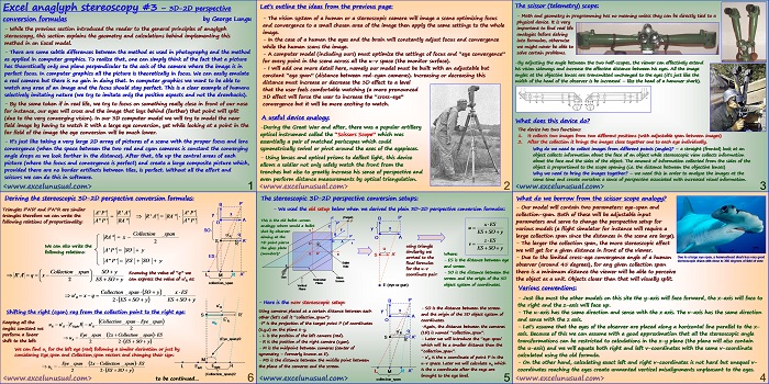
This section of the tutorial gives few more real life applications of the stereoscopic vision and also derives the stereoscopic 3D-2D perspective conversion formulas.
These formulas are based on the approximation that the that both right and left eyes observe the same v-coordinate.
Excel anaglyph stereoscopy #3 – 3D-2D perspective conversion formulas
by George Lungu
– While the previous section introduced the reader to the general principles of anaglyph
stereoscopy, this section explains the geometry and calculations behind implementing this
method in an Excel model.
– There are some subtle differences between the method as used in photography and the method
as applied in computer graphics. To realize that, one can simply think of the fact that a picture
has theoretically only one plane perpendicular to the axis of the camera where the image is in
perfect focus. In computer graphics all the picture is theoretically in focus.
We can easily emulate
a real camera but there is no gain in doing that. In computer graphics we want to be able to
watch any area of an image and the focus should stay perfect. This is a clear example of humans
selectively imitating nature (we try to imitate only the positive aspects and not the drawbacks).
– By the same token if in real life, we try to focus on something really close in front of our nose
for instance, our eyes will cross and the image that lays behind (farther) that point will split
(due to the very converging vision). In our 3D computer model we will try to model the near
field image by having to watch it with a large eye conversion, yet while looking at a point in the
far field of the image the eye conversion will be much lower.
– It’s just like taking a very large 2D array of pictures of a scene with the proper focus and lens
convergence (when the space between the two red and cyan cameras is constant the converging
angle drops as we look farther in the distance). After that, tile up the central areas of each
picture (where the focus and convergence is perfect) and create a large composite picture which,
provided there are no border artifacts between tiles, is perfect. Without all the effort and
scissors we can do this in software.
<excelunusual.com>
1
Let’s outline the ideas from the previous page:
– The vision system of a human or a stereoscopic camera will image a scene optimizing focus
and convergence to a small chosen area of the image then apply the same settings to the whole
image.
– In the case of a human the eyes and the brain will constantly adjust focus and convergence
while the human scans the image.
– A computer model (including ours) must optimize the settings of focus and “eye convergence”
for every point in the scene across all the u-v space (the monitor surface).
– I will add one more detail here, namely our model must be built with an adjustable but
constant “eye span” (distance between red-cyan cameras). Increasing or decreasing this
distance must increase or decrease the 3D effect to a level
that the user feels comfortable watching (a more pronounced
3D effect will force the user to increase the “cross-eye”
convergence but it will be more exciting to watch.
A useful device analogy:
-During the Great War and after, there was a popular artillery
optical instrument called the “Scissors Scope” which was
essentially a pair of matched periscopes which could
symmetrically swivel or pivot around the axes of the eyepieces.
– Using lenses and optical prisms to deflect light, this device
allows a soldier not only safely watch the front from the
trenches but also to greatly increase his sense of perspective and
even perform distance measurements by optical triangulation.
<excelunusual.com>
2
The scissor (telemetry) scope:
– Math and geometry in programming has no meaning unless they can be directly tied to a
physical device. It is very
important to find real life
analogies before delving
into formulas, otherwise
we might never be able to
solve certain problems.
-By adjusting the angle between the two half-scopes, the viewer can effectively extend
his vision sideways and increase the effective distance between his eyes. All the image
angles at the objective lenses are transmitted unchanged to the eyes (it’s just like the
width of the head of the observer is be increased – like the head of a hammer shark).
What does this device do?
The device has two functions:
1. It collects two images from two different positions (with adjustable span between images)
2. After the collection it brings the images close together one to each eye individually.
Why do we need to collect images from different points (angles)? – a straight (frontal) look at an
object collects information about the face of an object while stereoscopic view collects information
about the face and the sides of the object.
The amount of information collected from the sides of the
object is proportional to the scope opening (i.e. the distance between the objective lenses)
Why we need to bring the images together? – we need this in order to analyze the images at the
same time and create ourselves a sense of perspective associated with increased visual information.
<excelunusual.com>
3
What do we borrow from the scissor scope analogy?
– Our model will contain two parameters: eye-span and
collection-span. Both of these will be adjustable input
parameters and serve to change the perspective setup for
various models (a flight simulator for instance will require a
large collection span since the distances in the scene are large).
– The larger the collection span, the more stereoscopic effect
we will get for a given distance in front of the viewer.
Due to a large eye span, a hammerhead shark has very good
– Due to the limited cross-eye convergence angle of a human
stereoscopic vision with close to 360 degrees of field of view
observer (around 45 degrees), for any given collection span
there is a minimum distance the viewer will be able to perceive
the object as a unit. Objects closer than that will visually split.
Various conventions:
– Just like most the other models on this site the y-axis will face forward, the x-axis will face to
the right and the z-axis will face up.
– The u-axis has the same direction and sense with the x axis. The v-axis has the same direction
and sense with the z axis.
– Let’s assume that the eyes of the observer are placed along a horizontal line parallel to the x-
axis. Because of this we can assume with a good approximation that all the stereoscopic angle
transformations can be restricted to calculations in the x-y plane (the plane will also contain
the u-axis) and we will equate both right and left v-coordinates with the same v-coordinate
calculated using the old formula.
– On the other hand, calculating exact left and right v-coordinates is not hard but unequal v-
coordinates reaching the eyes create unwanted vertical misalignments unpleasant to the eyes.
<excelunusual.com>
4
The stereoscopic 3D-2D perspective conversion setups:
– We used the old setup below when we derived the plain 3D-2D perspective conversion formulas:
using triangle
the glass plate u ES SO y
similarity we
(monitor)? S A’ u Where:
S A’
arrived to the
– ES is the distance between eye
Bullet final formulas
E Hole and screen
for the u-v
– SO is the distance between the
coordinate pair:
Gun Glass
screen and the origin of the 3D
Horizontal
Screen
Plane
E (eye or gun) object system of coordinates.
Vertical
Plane
B P’
– Here is the new stereoscopic setup:
– SO is the distance between the screen
Using cameras placed at a certain distance between each y x
and the origin of the 3D object system of
other (let’s call it “collection_span”): A
O coordinates.
-P’ is the projection of the target point P (of coordinates
-Again, the distance between the cameras
(x,y,z) on the plane x-y.
u’R q
(LR) is named “collection_span”.
– L is the position of the left camera (red).
S A”
– Later we will introduce the “eye-span’
R’
– R is the position of the right camera (cyan).
which will be a smaller distance than the
– M is the midpoint between cameras (center of
“collection_span”.
symmetry – formerly known as E).
is the u coordinate of point P in the – u’R
– MS is the distance between the middle point between
u-v space. Later we will calculate uR which
the plane of the cameras and the screen.
is the u coordinate after the rays are
L M R A”
brought to the eye level.
<excelunusual.com> collection_span
5
Deriving the stereoscopic 3D-2D perspective conversion formulas:
B P’
Triangles P’A’R’ and P’A”R are similar
A’P’ R’ A’ A’P’
y x
triangles therefore we can write the
A”P’ RA” A”P’ A
following relations of proportionality: O
SO
Collection _span u’R q
RA”
2 S A’
R’
We can also write the
following relations:
Shifting the right (cyan) ray from the collection point to the right eye:
R R Right R
angles constant we 2
perform a linear Eye span
(Eye_span)/2
shift to the left:
We can find uL for the left eye (red) following a similar derivation or just by
considering Eye_span and Collection_span vectors and changing their sign:
M
Eye span
(Collection_span)/2
<excelunusual.com> to be continued…
6


