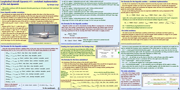
This section continues the worksheet implementation of the dynamics formulas.
Longitudinal Aircraft Dynamics #7- worksheet implementation of the real dynamics
by George Lungu
– This section continues with the dynamics formulas governing our 2D plane and their worksheet
implementation.
Some Reynolds number corrections:
– We introduced one single named cell for the Reynolds number (Re) when in fact there are two
different Reynolds numbers for the airplane, one for the main wing and one for the horizontal stabilizer.
We need two numbers in our model since the wing and the stabilizer have different size chords.
– We have to upgrade the worksheet to account for different Reynolds numbers for the two components.
– First we need to delete the name of the cell B3 in worksheet “Longitudinal_Stability_Model_4”.
– Click inside any cell => Insert => Name => Define => find the name you want to delete (“Re” in this
case).
– Rename cell B3 “Re_w” => select the cell =>
=> click in the name box in the upper left corner
of the worksheet => Type “Re_w” => Hit return.
– Rename cell B5 “Re_s” => select the cell =>
=> click in the name box in the upper left corner
of the worksheet => Type “Re_s” => Hit return.
– We also need to update the formulas which
included the old “Re” named cell. These formulas
are in the range T51:Y61 (see the next page).
The flying wing Atlantica – www.wingco.com
– In cell T51 replace “=IF(Re<$M51,N51,0)” with “=IF(Re_w<$M51,N51,0)”.
– In cell T52 replace “=IF(AND(Re<$M52, Re>=$M51),N51+(N52-N51)*(Re-$M51)/($M52-$M51),0)”
with “=IF(AND(Re_w<$M52, Re_w>=$M51),N51+(N52-N51)*(Re_w-$M51)/($M52-$M51),0)” then copy
T62 down to T60
– In cell T61 replace “=IF(Re>$M60,N60,0)” with “=IF(Re_w>$M60,N60,0)”
– Copy range T51:T61 to the right up to range V51:V61
– In cell W51 replace “=IF(Re<$M51,Q51,0)” with “=IF(Re_s<$M51,Q51,0)”.
– In cell W52 replace “=IF(AND(Re<$M52, Re>=$M51),Q51+(Q52-Q51)*(Re-$M51)/($M52-$M51),0)”
with “=IF(AND(Re_s<$M52, Re_s>=$M51),Q51+(Q52-Q51)*(Re_s-$M51)/($M52-$M51),0)” then copy
W62 down to W60
– In cell W61 replace “=IF(Re>$M60,Q60,0)” with “=IF(Re_s>$M60,Q60,0)”
– Copy range W51:W61 to the right up to range Y51:Y61 and you are finished.
The formulas for the Reynolds numbers:
– Reynolds numbers are used to characterize viscosity effects in aerodynamics. As the formula
below shows, the number is proportional to the product between the relative speed of the air
[m/s] with respect to the body, the length of the body in [m] (airfoil chord in this case) and
inversely proportional to the air viscosity which below 4000 meter is roughly constant.
Speed Chord
Re
Viscosity
– The formula can also be roughly expressed as:
where the speed is measured in [meter/second]
Re Speed Chord 70000
and the length is in meters
The formulas for the Reynolds numbers – worksheet implementation:
– Just like it was mentioned in the previous tutorial we must by any means avoid circular referencing.
– Since the Reynolds numbers are used in the “present” formula area to calculate the aerodynamic
forces, momentums, speeds and coordinates the Reynolds values will have to be calculated from “past”
speeds (to avoid circular referencing).
– We can use the following formula since we only have available the x and y components of the
aircraft speed in range D52:E52:
2 2
Re_ w 70000Chord _wing v 70000Chord _wing v v
plane plane_ x plane_ y
– Again, the x and y speed components in the above formulas are and have to be “past” components.
– Similarly we can write the formula for the horizontal stabilizer Reynolds number:
2 2
Re_ s 70000Chord _stabilizer v 70000Chord _stabilizer v v
plane plane_ x plane_ y
– B3: “=70000*Chord_wing*SQRT(D52^2+E52^2)”
– B5: “=70000*Chord_stabilizer*SQRT(D52^2+E52^2)”
The initial conditions:
– We need to insert the initial linear conditions (initial linear coordinates and linear speed x-y
components) formulas in range D47:H47 and the angular initial conditions in range I47:J47 (initial
angular speed of the airplane and initial airplane angle).
– We know the initial height, initial magnitude and angle of the initial speed as parameters and we
will assume that the initial angle of the airplane is the same as the initial speed angle.
– We have (as input parameters) the initial speed in polar representation (magnitude and angle) but we
need to calculate the Cartesian vector components of the initial speed so we need to do a conversion:
– D47: “=-Initial_speed*COS(RADIANS(Initial_angle))” – the minus sign comes from the fact that the
airplane is launched from right to left. The argument in the parentheses was being converted to radians
since the trigonometric functions treat their arguments as radians only.
– E47: “=Initial_speed*SIN(RADIANS(Initial_angle))”
– F47: “=0” – we will later set up the chart so that the x-scale will span only within negative
coordinates and the point of zero x-coordinate will be at the right most of the chart.
– G47: “=Initial_height” – that’s an input parameter
– I47: “=0” – we assume the airplane has a null angular (rotation) speed
– J47: “=Initial_angle”
– Please notice that the nature of cell H51 was modified together with the label above it to contain the
resultant pitching moment and not the angular acceleration as it did before.
The index calculation:
– The index is the integer number
counting the numbers of the “Do”
loop iterations within the
“Run_Pause” macro.
– K51: “=K52+1” – during every
loop iteration a copy from K50 to
K51 occurs and as a consequence
the index value is incremented by 1.
Creating two input entries for the fuselage drag:
– We have not introduced any aerodynamics effects (drag)
from the fuselage. We will insert two input parameter entries
(in cells B39 and B40), the fuselage frontal area and the
aerodynamic coefficient cd (we could adjust both of them).
– I had to move the “Time_step” cell two rows down to make
room for the new entries.
The formulas for the force calculations:
-An inventory of the forces acting on the aircraft is given below:
=> There are three drag forces always aligned with the speed of the aircraft but of opposite sense.
=> There are two lift forces always perpendicular to the speed of the aircraft.
=> The gravity which is applied in the center of mass and it is always vertical, pointing down.
– Let’s write the x-y components of these forces:
1
Based on Lift c Air_density Speed 2 Chord Span
l
2
We can write the wing lift force (below):
these general
1 2
c Air_density Speed Chord _wing Span_wing
equations from Drag d c Air_density Speed 2 Chord Span l _ wing
Lift
2 wing
2
the previous
1 2 2
Moment c Air_density Speed Chord Span
section: m
2
Knowing that the lift is always perpendicular to the speed of the aircraft vector we can decompose the lift in
2 2
x and y components:
c Air_density(v v )Chord _wing Span_wing sin(alpha _speed)
l _ wing plane_ x plane_ y
Lift
wing_ x
2
2 2
c Air_density(v v )Chord _wing Span_wing cos(alpha _speed)
l _ wing plane_ x plane_ y
Lift
wing_ y
2
The formulas for the Reynolds numbers:
– Using the same general equations, applying them to the main wing and the horizontal stabilizer then
decomposing them on the x and y axes we can write the final system (pay attention to the signs):
Lift c q Chord wing Span wing sin(alpha speed)
wing x l _ wing d
Lift c q Chord wing Span wing cos(alpha speed)
wing y l _ wing d
Lift c q Chord stabilizer Span stabilizer sin(alpha speed)
stabilizer x l _ stabilizer d
Lift c q Chord stabilizer Span stabilizer cos(alpha speed)
stabilizer y l _ stabilizer d
Drag c q Chord wing Span wing cos(alpha speed)
wing x d _ wing d
Drag c q Chord wing Span wing sin(alpha speed)
wing y d _ wing d
Drag c q Chord stabilizer Span stabilizer cos(alpha speed)
stabilizer x d _ stabilizer d
Drag c q Chord stabilizer Span stabilizer sin(alpha speed)
stabilizer y d _ stabilizer d
Drag c q Frontal area fuselage cos(alpha speed)
fuselage x d _ fuselage d
Drag c q Frontal area fuselage sin(alpha speed)
fuselage y d _ fuselage d
Gravityx 0
Gravity g m
y
Where q is the dynamic 1 2 1 2 2
q Air _density Speed _airplane Air_density(v v )
d plane_ x plane_ y
pressure expressed as: 2 2
To be continued…


We can make the same assessment in Civil Engineering