This is the second part of a tutorial explaining the creation of an “in-cockpit” flight simulator (versus the remote control simulator) model in Excel 2003.
This section introduces some basic piloting background and nomenclature.
![]()
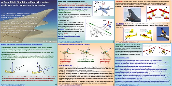
A Basic Flight Simulator in Excel #2 – airplane positioning, control surfaces and turn dynamics
by George Lungu
– This tutorial explains the basics of airplane positioning
which in our case it means the three angles
characterizing it’s position in flight: yaw, pitch and roll.
– It describes the control surfaces (rudders, ailerons and
elevator) in a typical airplane and the way they are
driven by the control devices (yoke and rudder pedals).
– It also briefly explains the dynamics of the aircraft turn
using the joystick only.
– All this information is useful in creating a simulator
which emulates a real plane.
<excelunusual.com> by George Lungu
Review of the three airplane rotation angles:
– The yaw angle (known as azimuth in astronomy or artillery)
defines rotation around the vertical – z axis (controlled by the rudder)
– The pitch angle or attitude (sometimes known as altitude) defines
rotation around the lateral – x axis (controlled by the elevator)
– The roll angle defines rotation around longitudinal – y axis
(controlled by the ailerons)
– Since our joystick has only two degrees of freedom we will only
control the pitch and roll angles since these are the most important
angles in controlling an airplane.
Airplane controls:
-An airplane has two main control devices: the yoke
(joystick or control stick in our case) and the rudder
pedals. The yoke has two degrees of freedom and it
controls the ailerons (by sideways movement) and
the elevator by (back and forth movement). The
rudder pedals have one degree of freedom and they
control the rudder.
– Most of the following pictures are from
https://www.rc-airplane-world.com/rc-airplane-controls.html
<excelunusual.com> 2
The rudder:
The rudder controls the yaw of the airplane. Since a good turn is realized by using the elevator and
ailerons the role of the rudder is important mainly at low altitude flying where not much roll angles are permitted
(landing in strong crosswind for instance). As opposed to a boat, the ruder is a secondary control device for an
airplane during regular flight (past a certain minimum altitude).
The elevator: The elevator controls the pitch of the airplane and it is used not only in changing the plane attitude
for purpose of gaining or loosing altitude but in turns too. The elevator is important even in executing constant
altitude turns.
<excelunusual.com> 3
The ailerons:
The ailerons control the roll of the
airplane and are mainly used in turns. The ailerons
are controlled by the sideways movement of the yoke
(or joystick in our case).
– When the joystick is pushed sideways the plane will
roll towards that side, and it will continue to do so
until the stick is brought to a symmetrical position.
How an airplane turns:
– The air exerts pressure on the wings of an airplane generating lift. The lift is the singe most important
aerodynamic force during the airplane flight due to the large area of the wings. The most important non-aerodynamic
force is the weight of the plane. In level flight at uniform speed these two forces are equal.
– During a turn, another large force on the airplane is the centrifugal force. Depending on the speed and turn radius, the
centrifugal force can be comparable or even larger than the weight of the plane.
– This is why, in a turn, the plane has to be tilted (rolled) at the proper angle, so that the three forces cancel each other. If
the roll is not enough the plane will “skid” outwards the intended turning circle and if the tilt is too large it will “slip”
inwards. A plane is not designed for much sideways movement or (outside skidding or inside slipping), so both previously
described situations can lead to dangerous instability issues.
– A good turn is initiated by first rolling the plane in the direction of the turn by a sideways move of the control stick and
then somewhat reducing the roll and increasing the pitch to a positive value (nose up). Maintaining the proper
combination of positive pitch (nose up) and roll in the direction of the turn is needed for the vector sum of the gravity, the
centrifugal force and the lift to balance (cancel) each other.
– The rudder does have a role and that is neutralizing the adverse yaw which is a yaw induced by the fact that the wing
external to the curve travels faster and hence has more air resistance applied to it than the wing internal to the curve.
This is a secondary effect and in our model we will not use a rudder since the mouse has only two degrees of freedom.
<excelunusual.com> 4
An illustration of roll angle effects during a left turn:
lift F
lift
centrifugal
G G G
Roll angle too small, Correct roll angle. The resultant Roll angle too large,
skidding situation ! of the transversal forces is null. slipping situation !
(stall-spin condition) (loss of altitude)
Pitch rate and roll rate:
A control surface will deflect the air stream and for a given speed will produce a force on the tip of the aircraft
proportional to the deflection angle. The force will produce a momentum proportional to the size of the force and
to how far the control surface is from the pressure center of he airplane.
Even though our first flight simulator model will be purely kinematic we need to try to emulate a real airplane
behavior. Any deviation in the position of a control device (i.e. joystick) will produce not an angle but a change in
the angle of the ship with a rate proportional to the amount of deviation of the control device from neutral point.
By this logic, we need to model the joystick effect such as if the stick is to the right 50 units the plane will roll to
the right with a certain rate (degrees/second). Keeping the stick at 100 units deviation to the left, the plane must
roll left wise with double that rate.
If we pull the stick from 0 (neutral) to 100 for instance, the pitch angle of the plane must increase (nose should
raise) with a rate double than in the case keeping the stick at 50 deviation from the neutral position.
<excelunusual.com> 5
Modeling the landscape coordinate change during the pitch rotation:
– Our flight simulator will be a 2D scatter chart containing the 2D mapping of a 3D wireframe landscape.
– The 3D-2D conversion was explained before on this blog, but we need to customize those perspective
coordinate conversion formulas exactly for our application.
– In a cockpit based flight simulator, the origin of the system of coordinates will be tied to the cockpit (more
precisely to the pilot’s eyes).
– The x-axis will be the longitudinal axis of the aircraft pointing forward, the y-axis will be horizontal (parallel
to the axis connecting the wings) pointing to the right and the z-axis will be vertical (parallel to the vertical
stabilizer) pointing upwards.
The above diagram shows a situation in which the plane is horizontal first and in the second situation is tilted
at a positive pitch angle (rotated around the y-axis). If the plane did not move at all except for the change
in the pitch angle, we need to find the relationship between the old coordinates and the new coordinates.
by George Lungu <excelunusual.com> 6


