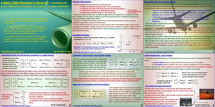
This section deals with a simple method of creating the appearance of scene movement during the flight.
Beside reviewing standandard rotation and translation formulas described before on this blog, the presentation begins to explain how to apply numerical-like methods to create a live and interactive model.
A Basic Flight Simulator in Excel #3 – calculating the scene rotation and translation as a result of the plane movement
by George Lungu
– This section of the tutorial explains a simple method
of creating the effect of a moving landscape below the
flying plane.
– The speed, and direction of movement as well as
various angles of perspective are to be controlled by
the virtual pilot using the joystick created in the
previous sections and a throttle button.
– The method has a lot in common with the general
procedure of creating dynamic numerical method
based models presented many times before in this blog.
<excelunusual.com> by George Lungu
Overview of the method:
– The basic method used in this model has the following steps:
=> Build a 3D wireframe landscape (done once at the beginning).
=> Translate and rotate the 3D image based on the input parameters
(loop through this
=> Convert the 3D image into a 2D perspective image
sequence while changing
=> Display the perspective image on a 2D scatter chart. input parameters)
– The last three steps are done while constantly changing perspective parameters in a continuous loop (one
linear coordinate and two angular coordinates) based on two input parameters coming from the joystick and
one input parameter coming from the throttle.
– The process is similar to the methods used in most of models on this blog and it is based on recurrent
calculations using results from the previous time step.
– Since the wireframe landscape has been created in the first section of this tutorial we will proceed to review
the formulas for translations, rotations and the 3D to 2D perspective conversion. Translation, rotation and 3D to
2D perspective conversion were analyzed before ( https://excelunusual.com/?s=3d ) and only a limited review
will be given in this section.
Coordinate translation:
y (x0+Dx,y0+Dy)
-The following coordinate transformation of point (x0, y0, z0) defines a translation by (Dx, Dy, Dz):
A
y0
(x , y , z ) (x Dx, y Dy,z Dz)
0 0 0 0 0 0
(x0,y0)
Dy
Illustration of a 2D translation operation (a 3D translation is harder to draw so I saved some effort by drawing it in 2D)
B
(0,0) x0 x
Dx
<excelunusual.com> 2
More details about the modeling method:
– There are two ways to model the apparent movement of the scene during the flight as seen from the cockpit.
– The easier way would be to start in an arbitrary position somewhere on the landscape. Every elementary time
step we do three operations with the scene image:
* move the scene backwards (along the y-axis) in the system of reference connected to the plane
* roll the scene in a direction opposite to the joystick horizontal deviation by an angular
elementary step proportional to the horizontal deviation of the joystick from neutral.
* rotate (pitch) the scene backwards or forward in a direction opposite to the joystick vertical
deviation by an angular elementary step proportional to the vertical deviation of the joystick
from neutral.
– This is very easy to program and it involves the copy-paste operation of the landscape vertex matrix to be done
during every time step in a loop.
– For this purpose we need three vertex matrices: an initial vertex matrix which contains the node coordinates as
seen from the plane just before takeoff, a current vertex matrix and a previous (past) vertex matrix. The current
vertex matrix will contain all the formulas corresponding to one translation (y) and two rotations (pitch and roll) of
the data from the past matrix.
– A macro will run an infinite conditional Do loop and paste the current matrix data in the past matrix during each
loop cycle (of course the copy-paste will be done after the current matrix was evaluated from the past matrix
data). The data for the rotation angles and the y-translation step length is taken from the joystick and throttle.
– Through this copy-paste operation, the macro would effectively model the passage of time and the movement
of the plane and its pilot through the scene as a function of the of the settings of the cockpit control devices
(joystick and throttle).
<excelunusual.com> 3
General background – scene rotation:
– In our model we encounter two types of of landscape rotation seen from a system of reference based in the cockpit :
* the pitch rotation which is a rotation around the transversal (x) axis of the airplane
* the roll rotation which is a rotation of the scene around the longitudinal axis (y) of the airplane
Based on a previous post – https://excelunusual.com/archive/2011/01/3d-2d-perspective-mapping-in-excel-part-2/ we will be giving the results of coordinate transformation trough a 2D rotation around origin.
We call x’ and y’ the new coordinates where
x’ cos()x sin() y
is the rotation angle and x and y are the
y’ sin() x cos() y
original coordinates before the rotation.
x’ cos()sin() x
Sometimes people like to put this in matrix form: sin() cos()
y’ y
Let’s choose the sign conventions:
– We choose the cockpit reference so that the plane flies towards the positive y
values (towards the monitor and perpendicular to it). The scene in this case will appear to approach the monitor.
– A positive roll of the plane will be a roll to the right. From the cockpit, the scene therefore will appear to roll to the left.
– A pitch is considered to increase when the plane raises its nose and in consequence the scene will appear to
drop in this system of coordinate bound to the cockpit.
The system of coordinate for the landscape is bound to the cockpit
<excelunusual.com>
Application of the formula to the 3D pitch rotation:
– The pitch rotation takes place around x-axis, therefore the x coordinate will be unchanged.
For a positive pitch angle the airplane will raise its nose, so the scene will tend to fall (z coordinate will drop).
The scene therefore will rotate opposite to the airplane (the pitch angle will
appear with minus in the scene rotation formula).
The coordinates in the formula refer to a point of the scene.
Verification:
In the formula above we can see that x’=x and which is what we need since the pitch rotation
occurs around the x axis. Also checking for the sign of the pitch angle, if the pitch angle is increasing and z=0
and y=1 from the formula z’ will decrease. In plain English the formula says that when the airplane raises it’s
nose an object in front of it will appear to be sinking which confirm the correct sign of the angle in the formula.
A positive airplane pitch is obtained by pulling the yoke or control stick. We need to make sure we take in
consideration that, namely to link the y-coordinate of the joystick with the negative of the pitch rate!!!
Application of the formula to the 3D roll rotation:
– The roll rotation takes place around y-axis, therefore
the y coordinate will be unchanged. For a positive roll
x”cos( ) 0sin( ) x ‘
roll roll angle (chosen to be to the right) of the airplane, the scene will rotate to the left. The scene therefore will rotate opposite to the way the airplane rolled.
y” 0 1 0 y ‘
z” sin( ) 0 cos() z ‘
roll
The coordinates in the formula refer to a point of the scene. x’, y’ and z’ are the coordinates after the pitch and x”, y” and z” are the coordinates after the roll.
<excelunusual.com> 5
Combining the pitch, the roll and the y-translation in a single formula:
Combining the two rotations formulas and adding a roll negative increment to the y coordinate (due to the movement of the airplane along the y axis) we get:
x” 0cos( ) sin( )sin( ) sin( )cos( ) x
This is the mathematical transformation that happens with a scene point as viewed from a cockpit reference
during an elementary time step of the flight (as airplane advances the image will approach the observer by Dy).
Knowing that this is actually part of a numerical method type of model, we can rewrite the above relationship:
x cos(D ) sin(D )sin(D ) sin(D )cos(D)x
Rate – the pitch and roll rate will later be chosen dependent on the pitch
Where we define position of the joystick, namely they will be directly proportional to
the following the the joystick coordinates
roll
Rate
roll
parameters: t – the speed of the plane will be controlled by the throttle
step
– we will discuss more about these parameters in the next tutorial
Dy
Speed
plane section
t
step
to be continued…
<excelunusual.com> 6


If you allow the value defining the horizon (to left and right) to fall outside the vertical range of your chart, you can get to quite high values of roll/tilt. Life gets difficult as you approach 90deg and inverted flight will require a complete revision of the chart. Gradient fills to lighten the sky color near the horizon and to fade out the land can look good but adjusting the angle with roll is just another headache.
I thought about all those things two years ago during the roller coaster age, but they are not worth my time. I have too much on my hands right now. Today I need to post another one and be done by the end of the week. I will install instruments (3 tilts) speed and altitude gauges few buildings perhaps and maybe some very basic physics. Within a month I will make an RC simulator and that will be way cooler, since the plane will fly around you. Then the scene is not so important and it is challenging to fly too. In-cockpit simulators are boring anyway unless one flies close to a very eleborate scene (which in Excel is unfeasible). I don’t want to get people bored with too much of this simulator stuff. The principle is much more important than some polish. There are lots of people who can program much better looking landscapes using all sorts of tools but there is not much explanation out there about the elementary principles behind perspective change. An open spreadsheet with simple formulas in a 2D form (rather that VBA linear code) I believe is very useful and that’s what I offer. Otherwise what do you think? Did you try it in 2003? I know in 2007 is extremely slow. The only chance for speed would be a 10×10. Peter, could you please reply to the next post, let’s move out of here?
Sounds promising.
My thoughts on the large rotations (with delta t not very small) is that the result depends on the sequence in which the controls are assumed to have been applied (pull up then roll does not result in the same balanced turn as roll, then pullup). The small angle approximation based upon angular velocities could even be a more accurate model for the situation where the two controls are actuated simultaneously.
I will have a further look at the 3-body system – the basis for studies on chaotic motion perhaps?
Peter, the planetary is completely a separate model but very polished.
I got the flight simulator running. Forgot an absolute reference and wasted few hours to find it. I’m not dissapointed!!! Great stuff but slow after I put it together (about 7 frames per second with display and 10 without). I might improve it a little but not much since I will be putting control instrument panel, perhaps a cannon and radar and of course some enemy UFO’s. It’s gonna be one of my best models.
I like polished.
Could you simplify the foreground detail if you superposed your scatter chart on a 2d area chart which infills the land/sky in much the same way as an artificial horizon?
I’ve been thinking for a ling time to introduce a giant ball and vary the center’position to get any angle possible and approximate the rim with a straight line given its huge size but your idea is far better and easier to implement. I don’t ever use area charts but I will figure it out.
Thanks Peter, that is a great idea. I’ve tried it and it will easily work for a 2D simulator (car) since it is hard to tilt. I can probably do some tricks though, but it won’t be easy.
So all is under control then. I was concerned by repeated manipulation of large arrays rather than getting the preliminaries done with the smaller transformation matrices. If the additional operations are fast then there is no issue.
On a separate issue, do you think it would make any difference to the behaviour of the simulation if you replace the large angle rotations used for the incremental update by small angle approximations? That is cosA := 1 and sinA := A.
Peter, I decided to finish the basic functionality before posting more. I am getting about 90 frames/second with joystick on and 41×41 verices, full processing (1 translation, 2 rotations + u-v conversion but no display yet). The display is supposed to bring the speed to mabe half or a third of that. I plotted the thing and it does not look right but I will figure it out by tonight. The joystick functionality is great though, I can loop and roll :-).
If the time step is very small it should be fine (doing cosA := 1 and sinA := A) but the game might be on the slower side. However you can live with some errors, no problem so the approximation must be all right even for larger time steps. On the other side I don’t think there is a speed problem since I calculate cos(pi()*pitch/180), sin(pi()*pitch/180), cos(pi()*roll/180), sin(pi()*roll/180) in a unique location in the worksheet and use those numbers in the rotation formulas. In my past experience I have not see significant differences in speed though by doing so but I think it’s a good practice. However if you pay attention to all the formulas and work it as a strategy throughout the sheet you can definitely improve speed. I did this on: https://excelunusual.com/3-body-planetary-system-with-options/.
You don’t have to but if you do you gain a lot. If you read carefully, I said in the tutorial that there are 2 ways. I didn’t go into details which is the second way but it is the standard way (without the paste). You don’t need to paste in the second one but you need to determine the 6 position parameters first (I would use a V shaped traveling form, apply the incremental controls and after that I would use basic trigonometry to determine the final 3 coordinates and 3 angles) and than apply back the 6 transformations to the whole image. It is a tutorial so I chose the simplest and natural way to do it (and easier to explain to beginners) which is 2 rotations + 1 translation (hence 1/2 calculations of the full method you are suggesting plus far easier to explain – most of people are light on math and geometry). The method I’ve chosen is the the smart way to do it, it does requires paste which is fast but it’s very light on calculations. Check out some of my heat models which run at 50-70 frames per second on 50×50 arrays using the same method. Of course charting really limits the speed to maybe only 30 fps. I started the full method (without paste) but I realized I would get bogged down in explanations for too many posts. I will do the full method but for the RC version (out of cockpit simulator). In the end I will benchmark them but it won’t be fair since the RC one does not change the landscape position. Thanks for the comment, George
George
I am still here. You have not convinced me of the need for three vertex meshes and cut and paste. Surely, it should be the transformation matrix (translations and rotations) that are incrementally updated so that the display is always derived by transforming the ground vertices.
Peter